Friday, 21 March 2014

cpu models


CPU Models
IBM and IBM Compatibles
Model NO. Word Size CPU SPEED (MHz) BUS SIZE (Bits)
8088 16 bits 5-10 8
8086 16 bits 6-12 16
80286 16 bits 6-16 16
80386DX 32 bits 16-40 32
80386SX 32 bits 16-25 16
80486DX 32 bits 25-66 32
80486SX 32 bits 16-25 32
Pentium 32 bits 60-166 32-64
Pentium Pro 23 bits 150-231 32-64

HARDWARE AND EQUIPMENT


11.1 INTRODUCTION

{A}
This section provides the design considerations, requirements, and examples for the following hardware and equipment: Tools, Drawers and Racks, Closures and Covers, Mounting Hardware, Handles and Grasp Areas, Restraints, Mobility Aids, Fasteners, Connectors, Windows, Packaging, Crew Personal Equipment, and Cable Management.

11.2 TOOLS

{A}

11.2.1 Introduction

{A}
This section includes the criteria for manual and power tools. It provides tool design requirements for normal operations and for planned and unplanned/contingency maintenance activities. Launch, entry, and temporary tool stowage requirements are also included along with examples of tool design solutions
(Refer to Paragraph 14.6.2, EVA Tools, for EVA-unique tool considerations and requirements.)
(Refer to Paragraph 12.3.2, Testability Design Requirements for information relevant to electronic and analytical test tools.)

11.2.2 Tool Design Considerations

{A}
Development of in-flight maintainable spacecraft systems must include consideration of tool selection, transport, stowage, ease of use, and criticality.
A satisfactory tool complement for future missions should include consideration of the following factors:
a. Tool Kit Contents - A tool kit should contain all the tools normally found in a tool collection for comprehensive usage as well as special tools required for special aerospace hardware. A standard tool kit should be developed that is based on known system requirements as well as past experience. This tool kit should include multi-purpose/multi-size tools. Despite the urge to reduce tool kit weight by not including sockets, wrenches, etc., that have no identified requirements, crewmembers have requested that all sizes be included as there are always unexpected needs that arise for the tool that was left behind.
b. Tool Transfer/Retention Device - A tool caddy should be provided to carry/translate tools from place to place and should be easily secured at the workstation. Transparent materials would be desirable so that the tools can be seen inside the caddy. Internal retention provisions are necessary to allow the crewmember to temporarily stow and retrieve small parts and equipment while the work is being done since containing and locating this equipment is a problem in microgravity.
c. Tool Commonality/Cost-effectiveness - A survey of previous tool development activities should be conducted prior to initiating costly tool development for suitable tools that are already in the inventory.
d. Tool Stowage Location - The stowage location of tool kits should be optimized for accessibility to workstations and maintenance workbenches.
e. Tool Unit Standards - Both English and metric standards must be accommodated in the tool kits. Some coding system on the tool should be used to readily distinguish English from metric.
f. Tool Inventory Control - Tools should be identifiable by the automated inventory control system.
(Refer to Paragraph 13.3, Inventory Control for specific inventory control design considerations and requirements.)

11.2.2.1 Power Tools Design Considerations

{A}
Power tools must meet the same design requirements as manual hand-tools regarding operability. Power tools should be used to accomplish repetitive manual tasks, such as disengaging captive fasteners or operating mechanical drive systems. Use of power tools offers enormous returns in reduced crewmember time and effort and ease of operation.
(See Paragraph 14.6.2, EVA Tools, for design considerations pertaining to power tools used in an EVA environment.)
Power tools subject the crewmember to specific hazards and stresses that should be considered. Specific considerations include rotating components, electrical shock, heat generation, flying particles or sparks, inadvertent power activation, and hazards to the nonoperating hand. Power tool design should avoid the use of brush type motors since they may create hazardous EMI (electromagnetic interference) and provide an ignition source.
(Refer to Paragraph 6.4, Electrical Hazards, for electrical safety design considerations and requirements.)
Some types of tools create unique problems. Typical of these are soldering tools, which can cause burns if the operator touches a tip that is still hot or lays the tool on flammable materials.
It should be noted that the standard practice has been to accept many of the above hazards as part of the job and to place the burden of protection on users, i.e., to recommend wearing eye protectors, using special electrical grounding devices, wearing gloves, etc. In many cases these are the only methods available to reduce the hazard potential. However, the designer should, in each new tool design, review such hazards and attempt to remove them whenever possible in the design. When this cannot be accomplished, the designer should assume the responsibility for providing appropriate warning labels on the tool and/or include properly worded warning instructional materials with the tool. The designer should know better than anyone else what hazards a new tool presents.
(Refer to Paragraph 6.2, General Safety, for more detailed safety design considerations.)
For rechargeable battery-powered tools, the inventory of spare power packs and the location of recharge stations are important design considerations.

11.2.2.2 Body Stabilization When Using Tool Design Consideration

{A}
Previous orbital missions have indicated that, when properly restrained, the crewmembers can perform most manipulative operations on orbit using standard tools as effectively as these operations can be performed in an Earth environment. In many in-space maintenance operations, this adequate restraint was not anticipated in the design of the equipment. This led to a lot of wasted time and crew frustration. Therefore, it is very important that adequate interface designs (i.e., designing the payload for EVA and IVA servicing), adequate body restraints, and a moderate complement of hand tools be provided so space system servicing requirements can be met.
(Refer to Section 12.0, Design for Maintainability, for general and specific requirements for designing payloads for servicing.)
(Refer to Paragraph 9.2.4.2.3, Workstation Restraints and Mobility Aids, and to Paragraph 14.4.3, EVA Workstations and Restraints, for specific requirements related to integrating restraints and workstations.)

11.2.3 Tool Design Requirements

{A}
The tool design requirements in the following subsections apply to tools that are intended to be used to activate, operate, maintain, and deactivate manned and unmanned equipment in both EVA and IVA environments.
(Where there are EVA-unique tool design requirements, they are so noted with reference to Section 14.0.)

11.2.3.1 Hand and Tool Integration Design Requirements

{A}

11.2.3.1.1 Tool Handgrip Size and Shape Design Requirements

{A}
Power and manual hand tools shall comply with the following handgrip size and shape requirements:
(Refer to Paragraph 6.5.3, Touch Temperature Design Requirements for specific touch temperature criteria.)
a. Gripping Surface - Hand gripping surfaces that minimize abrasion to the EVA glove material shall be provided on handles of tools.
b. Sleeve Type Adapters - If sleeve-type handle cover adaptors are used, they shall be adequately secured so they will not slip, rotate, or come off.
c. Orientation - Tool handles shall be oriented to allow the operator's wrist to remain in the most natural position while force or guidance inputs are applies.
d. Auxiliary Controls - If an auxiliary control on the tool must be manipulated while the operator is holding the tool, the control shall be located where:
1. The thumb or finger of the holding hand can manipulate the control without disturbing the tool/fastener holding position.
2. Unintentional or inadvertent control operation is impossible.

11.2.3.1.2 Tool Handedness Design Requirements

{A}
The following requirements apply to handheld manual tools and handheld power tools:
a. Tool Operation - All general purpose hand tools shall be one-handed operable insofar as practical.
b. Tool Installation/Alignment - One hand only shall be required for tool installation and alignment.
c. Tool Handle Design - Tool handles shall be designed to allow the operator to use either the left or right hand.

11.2.3.1.3 Tool Actuation Forces and Direction of Action Design Requirements

{A}
All hand tools shall comply with the following:
a. Actuation Force - Hand tools shall require an actuation force of less than 89N (20 lbs.) or a torque of less than 15 Nm (11 ft-lbs).
b. Throw Angles - Ratcheting tools shall be capable of providing torque with a minimum throw angle of 45 degrees.
c. Plier-Type Tools - Plier-type tools shall be spring-actuated in the open direction to permit one-handed operation.
d. Driver-Type Tools - Driver-type hand tools shall not require a push force to maintain tool engagement while providing torque.

11.2.3.2 Tool Commonalty Design Requirements

{A}
To ensure that the tool complement is kept at a minimum, the following requirements shall apply:
a. Tool Quantity - The number of different types of tools shall be minimized.
b. Standard Attaching Hardware and Fasteners - Size and type of attaching hardware and fastener head configurations shall be standardized throughout the vehicles to limit the number and kind of tools required to perform maintenance tasks.
(Refer to Paragraph 11.9, Fastener Design Requirements, for specific fastener-to-tool interface requirements.)
c. Special Tools - The number of different and special tools required for maintenance shall be minimized.
d. For every type and size of fastener used onboard, a corresponding tool(s) shall be available for removal/replacement.
(Refer to Paragraph 11.9.3.1, Fastener Design Requirements for specific considerations and requirements).

11.2.3.3 Tool Tethering/Retention Design Requirements

{A}
The following tool tethering and tool retention requirements shall be apply:
a. Tool Restraints - A means shall be provided on all tools for restraining the tool during use.
b. Tool Transporter Devices - Tool carriers shall be provided to transport tools and to retain these tools during the maintenance activity.
c. Retention of Small Parts - Tool carriers/transfer devices shall provide a means of retaining small parts and attaching hardware. Items retainable in this manner shall be visible for retrieval.
d. Tool Restraint During Translation - Tools shall be restrained in the tool carrier/transfer device with sufficient force to prohibit detachment during translation.
e. Tool Carrier Attachment - Tool carriers and tool retention devices shall have provisions to attach the device to the crewmember or to adjacent structure or equipment.
(See Paragraph 11.7.3.3, Equipment Restraint Design Requirements, for other applicable restraint requirements.)
f. Inadvertent Tool Disassembly - A means shall be provided to prevent inadvertent tool disassembly while installing, using, removing, or transporting the tool.

11.2.3.4 Tool Stowage Design Requirements

{A}
Tool stowage must allow for ease of retrieval, retention, identification, and replacement. To accomplish this, the following requirements shall apply:
a. General - A systematic approach shall be used in stowing tools and maintenance aids throughout the space module.
b. Stowage Provisions - Provisions for launch, entry, and temporary in-flight stowage shall be provided.
c. Stowage Location:
1. Specialized tools shall be stowed in areas which correspond to their functional applications.
2. All general-purpose tools shall be grouped in one specific area.
d. Tool Stowage List - A tool summary or listing of the entire tool inventory, including stowage locations, shall be available onboard the space module.
e. Tool Arrangement in Stowage Container - A systematic approach shall be used in the arrangement of tools in the tool kit.
f. Temporary Stowage at Work Area - A systematic approach and a methodical layout of tools at the work area shall be required.
(Refer to Paragraph 10.12.3, Stowage Design Requirements, for other specific stowage requirements.)

11.2.3.5 Tool Labeling and Identification Design Requirements

{A}
Tool and tool stowage labeling and identification requirements shall comply with the following:
(Refer to Paragraph 9.5.3, Labeling and Coding Design Requirements for detailed labeling and coding requirements.)
a. Selection of Names for General Tools - Tool names shall be identical to those names called out on the tool/ tool label and, in all cases, will be the most common definitive name recognizable by the crewmembers.
b. Selection of Names for Specialized Tools - Specialized tool nomenclature shall describe the specific task it is intended to accomplish and shall not be identified with the equipment it is servicing.
c. Identification of Specialized Tools - When special tools are absolutely necessary, they shall be coded and/or marked to indicate intended use.
d. Tool Labels - Prominent labels shall be provided adjacent to each tool in the stowage container/kit if the tool is not readily recognizable.
e. Tool Metric/English Identification - All tools shall be labeled or coded to indicate whether the tool is sized in metric or English units.
f. Tool Inventory Control Labeling - Tools shall be tracked by an automated inventory control identification system.
(Refer to Paragraph 13.3.3, Inventory Control Design Requirements, for specific requirements.)
g. EVA Tool Compatibility - IVA tools that are EVA compatible shall be so identified.

11.2.3.6 Tool Access Design Requirements

{A}
The following tool access volume and operational constraints requirements are applicable to both IVA and EVA hardware design (refer to Figure 11.2.3.6-1 for IVA requirements and Paragraph 14.6.2.3 for EVA requirements):

Figure 11.2.3.6-1 Tool Access Requirements (IVA)

Sketch of a torquing tool and clearance requirements from adjacent obstructions
Notes:
Minimum tool head clearance must be adequate for insertion, actuation, and removal of drive end of tool. Minimum 0.76 cm (0.3 in) tool head engagement height. Tool handle offset minimum 7.6 cm (3 in), maximum 35.5 cm (14 in). Minimum 7.6 cm (3 in) tool handle clearance (measured from end of handle to nearest obstruction). Minimum of 180 degrees clearance for lever type tools. Minimum of 360 degrees clearance for driver type tool.
See Figure 14.6.2.3-1 for EVA requirements.
Reference: 320; NASA-STD-3000 12b
a. Tool Head Clearance - Where only tool access is required, clearance shall be provided around the fastener or drive stud for insertion, actuation, and removal of the drive end of the tool.
b. Tool Handle Clearance - A minimum of 7.6 cm (3 in.) shall be provided for clearance between a tool handle engaged on a fastener or drive stud and the nearest piece of hardware. The tool handle should be able to maintain this clearance through a full 180 deg. swept envelope.
c. Tool Head-to-Fastener Engagement Height - The tool socket/fastener head engagement height shall be sufficient to lower the bearing loads on the fasteners and tool below the failure limits of the materials.
d. Tool Handle Offset - The maximum tool offset between the tool handle and the tool head shall be 35.5 cm (14 in.).
e. Access for Tools - Minimum tool access clearance for hand tool actuation is given in Figure 11.2.3.6-2.

Figure 11.2.3.6-2 Minimal Clearance for Tool-Operated Fasteners

Opening dimensions Task
Sketch of a hand using a common screw-driver A 117 mm (4.6 in) B 107 mm (4.2 in) Using common screw-driver with freedom to turn hand through 180°
Sketch of a hand using pliers A 133 mm (5.2 in) B 115 mm (4.5 in) Using pliers and similar tools
Sketch of a hand using a T-handle wrench A 117 mm (6.1 in) B 107 mm (5.3 in) Using T-handle wrench with freedom to turn wrench through 180°
Sketch of a hand using an open-end wrench A 203 mm (8.0 in) B 135 mm (5.3 in) Using open-end wrench with freedom to turn wrench through 62°
Sketch of a hand using an Allen-type wrench A 122 mm (4.8 in) B 155 mm (6.1 in) Using Allen-type wrench with freedom to turn wrench through 62°
Notes:
1. Refer to Figure 12.3.1.2-1 for other hand and arm access hold dimensions.
2. Refer to Figure 11.2.3.6-1.
Reference: 1, p. 4.4-7; NASA-STD-3000 27

11.2.3.7 Special Tool Features Design Requirements

{A}
Compliance with the following special features shall be required when designing or providing tools for IVA servicing and maintenance tasks:
a. Non-sparking Tools - Non-sparking materials shall be required for general purpose tools.
b. Nonconductive Tools :
Refer to Paragraph 6.5.2, Touch Temperature Design Requirements, when tools are to be used in extremely hot or cold temperature areas.)
(Refer to Paragraph 6.4.3, Electrical Hazards Design Requirements, for requirements for insulation protection against electrical hazards.)
c. Finish - Tools shall be capable of being refinished in flight in order to remove burrs.
(Refer to Paragraph 6.3.3, Mechanical Hazards Design Requirements, for burrs, corners, edges, and protrusion design requirements.)
d. Battery Pack :
1. Power tools shall be designed so the battery packs can be replaced at the worksite.
2. Power tools using battery packs shall have a level-of-charge indicator or an indication as to when a battery pack is required to be replaced or recharged.
3. Hazards associated with charging and stowage of rechargeable batteries (such as toxic or flammable offgassing, leakage of corrosive electrolytes or high temperatures) shall be addressed and controlled.

11.2.4 Example Tool Design Solutions

{A}
Examples of previously used IVA tools are included in this section to illustrate how tools are constructed, stored, identified, transferred, tethered, or restrained at work locations. These proven examples should be considered when developing new tools and maintenance aids for future missions.
(Refer to Paragraph 14.6.2.4, Example EVA Tools Design Solutions, for description of EVA tools.)

11.2.4.1 Example Manual Tools

{A}
The following IVA tools have flown successfully on STS missions:
(Refer to Reference 150 for complete details on STS tools.)
a. Off-the-Shelf STS IVA Tools - Examples of off-the- shelf IVA tools, stowage, and identification methods are shown in Figure 11.2.4.1-1, Figure 11.2.4.1-2 and Figure 11.2.4.1-3.
b. Stowage Provisions - Stowage provisions are shown in Figure 11.2.4.1-1, Figure 11.2.4.1-2 and Figure 11.2.4.1-3. Tool trays include provisions for individual hand tools in the trays by providing cushions fabricated from white foam with a fine cell structure. Very accurate cuts were required to provide adequate retention for launch, in-flight, and enter environments. Tools were individually identified at each location. The foam is coated with a fire-retardant seal material.
c. Tool Kits and Tool Pouches - Tool kits and tool pouches (Figure 11.2.4.1-3) were used to retain small tool packages to worksites. These kits or pouches had provisions (snaps, straps, Velcro, etc.) for attaching the units to the worksite structure.

Figure 11.2.4.1-1 Examples of IVA Hand Tools, Stowage, and Identification

Sketches of tool locker and tool trays
Reference: 150, p. 3.23-10; NASA-STD-3000 13

Figure 11.2.4.1-2 Miscellaneous IVA Tool Stowage Examples

Sketches of a tool kit tray with examples of things stored inside (i.e., gray tape, velcro, fuse kit, etc)
Reference: 150, p. 3.23-14; NASA-STD-3000 14

Figure 11.2.4.1-3 Tool Translation and Retention Pouch Examples

Sketches of a pin kit and tool pouch demonstrating the storage of tools for translation
Reference: 150, p. 3.23-16 and -18; NASA-STD-3000 15

11.2.4.2 Example Power Tools

{A}
The vacuum cleaner is an example of an IVA power tool used on Skylab, Shuttle and Spacelab missions. The vacuum cleaner is a tool which is presently used for cleaning intake screens to black box cooling fans, orbiter air filters, and Spacelab Environmental Control System (ECS) filters. The unit is also used for general housekeeping chores.
(Refer to Paragraph 13.2 Housekeeping, for housekeeping design considerations and requirements.)
Another example of IVA power tools is the EVA Power Tool utilized to remove panel fasteners in an IVA mode.
(Refer to Paragraph 14.6.2.4.2, Example EVA Power Tool Design Solutions, for a description of this STS EVA power tool.)

11.3 DRAWERS AND RACKS

{A}

11.3.1 Introduction

{A}
This section provides the design considerations and requirements for drawers and racks. This includes the definition of size, interfaces, operating mechanisms, location relative to workstations and traffic patterns, ease of use, restraints, and utility connections.
Stowage drawers are a specific type of stowage compartment.
(Refer to Paragraph 10.12, Stowage Facility for general and specific stowage design considerations and requirements that are also applicable to drawers.)
Equipment drawers are a specific type of equipment mounting hardware that are designed to facilitate equipment replacement and maintenance.
(Refer to Section 12.0, Design for Maintainability, for general and specific maintainability design considerations and requirements that are also applicable to equipment drawers.)

11.3.2 Drawer and Rack Design Considerations

{A}
There are two types of drawers that are used in space modules: storage drawers and equipment drawers. Stowage drawers and equipment drawers are similar in that both are mounted in racks, cabinets, or housings; they are designed to slide out to provide the user with access to their contents; they stay in the open position until pushed back into the stowed position; and they can be removed from the housing/cabinet by some secondary unlatching operation. They are distinguished from each other by the fact that stowage drawers are used to stow normally removable contents, whereas equipment drawers are used to mount subsystem components. The contents of a stowage drawer can be removed or replaced easily as the contents are restrained by soft restraints (e.g., foam cutouts, elastic bungee cords, etc.) which can be easily manipulated by hand without using any tools. The contents of an equipment drawer, on the other hand, usually need to be removed or replaced using a hand tool. Equipment drawers always have utility connections(such as power and thermal control), whereas stowage drawers generally have none.
Because of their similarities, stowage and equipment drawers need to be designed with many of the same design considerations and requirements.
The drawer becomes a workstation when the crewmember has a need to access its contents. This requires adequate crewmember restraint while using it, handles and latches that are designed for one-handed operation, ease of access to the contents, restraint of the drawer/rack in the opened position, Commonalty with other drawers/racks, etc.
Racks are structural housings into which equipment drawers and other types of equipment mounting hardware are installed. The racks are either single-wide units (i.e., they are designed to mount a single stack of equipment drawers) or they are double-wide units (i.e., they are designed to mount a side-by-side stack of equipment drawers so they can house a double-wide equipment drawer). The racks generally have built-in utility (e.g., thermal, power, data) distribution systems which are designed to provide interfaces with each of the installed equipment drawers. The rack's utility system interfaces with the space module's utilities distribution system at standardized locations.
In the closed position, drawers should be designed to contain particulates, liquids, or gaseous matter. Drawer opening and closing mechanisms should incorporate some form of motion damping to prevent disturbance of the micro-g environment and to hold the drawer at intermediate positions for zero-g operations. The use of magnetic latches on drawers and doors should be avoided if at all possible

11.3.3 Drawer and Rack Design Requirements

{A}

11.3.3.1 Drawer and Rack Interfacing Requirements

{A}
Stowage drawers, equipment drawers and racks shall be designed to provide the following interfacing features:
a. Size :
1. Unless prohibited by functional needs, all racks shall be designed to house single-wide drawers (and other types of equipment mounting hardware) that shall be 48.26 cm (19.00 in) wide or double-wide drawers that shall be 96.52 cm (38.00 in) wide.
(Refer to Paragraph 2.3.2, Standardization Design Requirements, for the general standardization requirements.)
2. If equipment is intended to be launched and returned in the Shuttle stowage lockers, it shall be sized per Figure 11.3.3.1-1.
b. Location Related to Traffic Patterns - Racks that require frequent drawer deployment shall be located in areas that do not have high traffic.
(Refer to Paragraph 8.7.3, Traffic Flow Design Requirements, for general and specific requirements related to blocking traffic patterns.)

Figure 11.3.3.1-1 Shuttle Stowage Locker Dimensions

Figure of Shuttle Stowage Locker Dimensions
Note: Tolerances: 0.0002 cm (0.0001 in) Small tray; 0.0005 cm (0.0002 in) Large tray
Reference: 350, Figure 4 and 5; NASA-STD-3000 229
c. Unobstructed Volume for Use - Provide adequate clearance such that the drawers can be opened, removed, and replaced without obstructions from adjacent hardware.
d. Easily Removable - Rack and drawer interfaces shall be designed such that the drawers can be removed from their rack or cabinet along a continuous straight or slightly curved path without using tools.
e. Limit Stops:
1. Provide limit stops that will prevent the drawer from being unintentionally pulled out of the rack.
2. The limit stops shall be designed to hold the drawer in the full open position.
3. The limit stops shall be capable of being disengaged without using a tool to enable drawer removal.
f. Drawer Movement Forces - Drawer opening/closing or removal/installation shall not require a force greater than 156 N (35 lbs).
(Refer to Paragraph 4.9.3, Strength - Design Requirements, for crewmember strength requirements.)
g. Alignment Guides - Provide guide pins or equivalent to aid in alignment when replacing a drawer into its rack or cabinet.
(Refer to Paragraph 11.5.3.2, Alignment Devices Design Requirements, for detailed requirements.)
h. Shuttle Compatibility - If equipment is intended to be launched/returned within the Shuttle, it shall be designed for compatibility with the Shuttle stowage system.
i. Stowage Trays
1. Provide limit stops that will prevent the tray form being unintentionally pulled out of the drawer.
2. The limit stops shall be designed to hold the tray in the 3/4 open position.
3. The limit stops shall be capable of being disengaged without using a tool.

11.3.3.2 Design Requirements Common to Both Stowage and Equipment Drawers

{A}
In addition to the requirements given in Paragraph 11.3.3.1, all stowage and equipment drawers shall be designed to provide the following features:
a. Latches/Handles/Operating Mechanisms - All latches, handles, and operating mechanisms shall be designed to be easily latched/unlatched and opened/closed with one hand by the entire crewmember population without having to use any operating instructions.skip references
(Refer to Paragraph 3.3, Anthropometrics and Biomechanics-Related Design Data, for crewmember population anthropometrics.)
(Refer to Paragraph 4.9.3, Strength Design Requirements, for crewmember strength capabilities.)
(Refer to Paragraph 11.6.3, Handle and Grasp Area Design Requirements, for handle and grasp area configuration requirements.)end of references
b. Latch/Unlatch Status - The design shall be such that it is obvious when the drawer is not fastened/locked when in the closed position.

11.3.3.3 Stowage Drawer Design

{A}
In addition to the requirements given in Paragraphs 11.3.3.1 and 11.3.3.2, stowage drawers shall be designed to meet the following requirements:
a. Restraint of Contents:
1. Drawer contents shall be restrained in such a way that the items shall not float free when the drawer is opened, or jam the drawer so it cannot be opened or closed.
2. Drawer contents shall be restrained in such a way that the contents can be removed/replaced without using a tool.
(Refer to Paragraph 11.7.3, Equipment Restraints, for specific restraint requirements.)
b. Arrangement in Housing/Cabinet - Drawers shall be arranged within their housing/cabinet such that the most frequently accessed drawers are in the most accessible locations.
c. Access to Contents - The contents of drawers shall be arranged such that the contents are visible and accessible when the drawer is in the open position.
d. Identification of Contents - In the stowed position, the contents of drawers shall be identified by labeling.
(Refer to Paragraph 9.5.3, Labeling and Coding Design Requirements, for specific requirements.

11.3.3.4 Equipment Drawer Design Requirements

{A}
In addition to the requirements given in Paragraphs 11.3.3.1 and 11.3.3.2, equipment drawers shall be designed to meet the following requirements:
a. Utility Connections:
1. The utility connections shall be designed to be easily disconnected/connected when the drawer is in the fully opened position.
(Refer to Paragraph 11.10.3, Connector Design Requirements, for general and specific connector design requirements.)
2. If the utility connection is via a flexible umbilical, sufficient cable length shall be provided such that the drawer can be fully opened without disconnecting the cables.
(Refer to Paragraph 11.14.3, Cable Management Design Requirements, for general and specific design requirements.)
b. Equipment Layout on Rack:
1. Components shall be mounted in an orderly array on a two-dimensional surface, rather than stacked one on another (i.e., a lower layer shall not support an upper layer).
2. Items of the same or similar form, but having different functional properties, shall be mounted with a standard orientation throughout the unit, but shall be readily identifiable and distinguishable, and shall not be physically interchangeable.
3. Delicate items shall be located or guarded so that they will not be susceptible to damage while the unit is being handled or maintained.

Wednesday, 19 March 2014

Hardware Troubleshooting Tools

Hardware Troubleshooting Tools

              The level of troubleshooting most often performed on PC hardware is
exchanging Field Replaceable Units (FRUs). Due to the relative low cost of
computer components, it is normally not practical to troubleshoot failed
components to the IC level. The cost of using a technician to diagnose the
problem further, and repair it, can quickly exceed the cost of the new replacement
unit.
However, a few hardware diagnostic tools can be very helpful in isolating
defective hardware components. These tools include
➤ Software diagnostic disk
➤ Multimeter
➤ Cable tester
➤ POST card
Software Diagnostic Packages
Several commercially available disk-based diagnostic routines can check the
system by running predetermined tests on different areas of its hardware.
The diagnostic package evaluates the response from each test and attempts
to produce a status report for all of the system’s major components. Like the
computer’s self-tests, these packages produce visual and beep-coded error
messages. Figure 3.1 depicts the Main menu of a typical self-booting software
diagnostic package.

                   A typical software diagnostic main menu

This menu is the gateway to information about the system’s makeup and
configuration, as well as the entryway to the program’s Advanced Diagnostic
Test functions. You can find utilities for performing low-level formats on
older hard drive types and for managing small computer system interface
(SCSI) devices through this menu. In addition, options to print or show test
results are available here, as is the exit point from the program.
The most common software-troubleshooting packages test the system’s
memory, microprocessor, keyboard, display monitor, and the disk drive’s
speed. If at least the system’s CPU, disk drive, and clock circuits are working,
you might be able to use one of these special software-troubleshooting packages
to help localize system failures. They can prove especially helpful when
trying to track down non-heat-related intermittent problems.
If a diagnostic program indicates that multiple items should be replaced,
replace the units one at a time until the unit starts up. Then replace any units
removed prior to the one that caused the system to start. This process
ensures that there are not multiple bad parts. If you have replaced all the
parts, and the unit still does not function properly, the diagnostic software is
suspect.

Sunday, 16 March 2014

hardware Adding a disc drive

7 Adding a disc drive.

There is never enough disk space. The minute a new disk is added to the system, it is half full, or so it seems. Getting users to clean up their disk space is as difficult as getting a teenage boy to clean up his room. Therefore, the system administrator will occasionally have to install new disk drives.

7.1 Disc drive terminology.

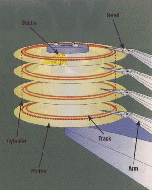
  • The circular plate coated with magnetic media is called a platter - drives usually have several platters
  • The heads ride on a microscopic film of air on the platter surface - all heads move together
  • The platters spin rapidly and the heads move in and out to position on a track - this action is called seeking
  • Each track is made up of a number of sectors
  • The collection of tracks under all of the heads is called a cylinder
  • When a head touches the surface of a platter, it is called a head crash - this is a Bad Thing (go buy a new disc and get out your last backup!)
  • Discs are logically divided up (by groupings of cylinders or sectors) into partitions -partitions usually overlap
  • File systems occupy entire partitions (not all partitions have file systems, e.g. the swap partition)
  • Every file system has a superblock which contains information such as the file system's label, size, and total number of inodes
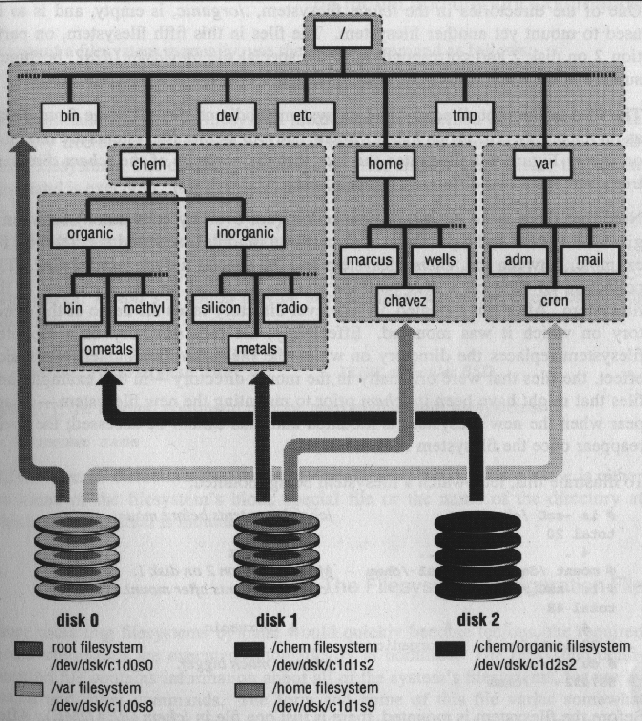
This diagram shows an idealized disc drive. Here is an example of how several file systems on three disc drives might be mounted.

7.2 Steps in adding a disc drive.

  • Make a device entry in /dev for the new disc (use /dev/MAKEDEV)
  • Make an entry in /etc/disktab (4.2 BSD) or /etc/device.tab (System V.4) for your new disc
  • Set the SCSI address to a legal, unused SCSI id
  • Connect the drive to the SCSI bus
  • Make sure the disc is formatted/partitioned correctly
  • Make files systems using newfs or mkfs
  • Make an entry in /etc/fstab for the new partitions
  • Mount the new partitions
  • Transfer file systems (if necessary)
  • Do site specific configurations (e.g., BSD quotas)

7.3 Commands for determining device names/numbers

  • SunOS 4.x/5.x - dmesg
  • IRIX - hinv
  • OSF/1 (Digital Unix), Ultrix - uerf

7.4 Commands for partitioning/formatting drives

  • SunOS 4.x/5.x - format
  • IRIX - fx
  • OSF/1 - disklabel (gets partition information from /etc/disktab)
  • Ultrix - chpt, rzdisk
  • Linux - fdisk

7.5 Commands for examining partition information

  • SunOS 4.x - dkinfo
  • SunOS 5.x, IRIX - prtvtoc
  • Ultrix - chpt
  • Linux - fdisk

7.6 Example BSD partitioning.

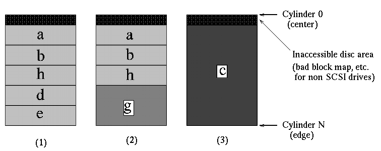
BSD systems usually use 8 partitions (labelled "a" through "h")
Example Eagle disc partitions 
------------------------------------
Partition  Cylinders  Typical use     
------------------------------------
a          0-15       /               
b          16-86      Swap            
c          0-841      Entire disc     
d          391-407    Alternate Root  
e          408-727                    
f          728-841                    
g          391-841    /usr            
h          87-390                     
------------------------------------
There are several possible ways of creating file systems on these partitions. Here is a diagram of three alternatives.

7.7 Example System V partitioning.

System V systems number their partitions 0 through 7. (Example from IRIX system)
# prtvtoc c0t0d0s2
* c0t0d0s2 partition map
*
* Dimensions:
* 512 bytes/sector
* 84 sectors/track
* 15 tracks/cylinder
* 1260 sectors/cylinder
* 1658 cylinders
* 1656 accessible cylinders
*
* Flags:
* 1: unmountable
* 10: read-only
*
* First Sector Last
* Partition Tag Flags Sector Count Sector Mount Directory
 0 2 00 0 103320 103319 /
 1 3 01 103320 132300 235619
 2 5 00 0 2086560 2086559
 5 6 00 235620 1106280 1341899 /opt
 6 4 00 1341900 437220 1779119 /usr
 7 4 00 1779120 307440 2086559 /usr/openwin

7.8 The Berkeley /etc/disktab file.

Here is an example of an /etc/disktab file used here in C&C for Ultrix systems. The descriptions of the entries can be found in the man pages for disktab (see "man disktab").

7.9 The SunOS format.dat file.

SunOS uses a file called format.dat. This example is from the sun-managers email list.

7.10 /etc/fstab file (System V).

blck-spcl-file mnt-loc [fstype] [options]
/dev/root / efs rw,raw=/dev/rroot 0 0
/dev/usr /usr efs rw,raw=/dev/rusr 0 0

7.11 /etc/fstab file (4.3 BSD).

blck-spcl-file mnt-loc fstype opts dump-freq passno
/dev/sd0a / 4.3 rw,noquota,noauto 0 1

7.12 /etc/fstab file (ULTRIX).

blck-spcl-file:mnt-loc:type:dump-freq:passno:fstype:options
/dev/ra0a:/:rw:1:1:ufs::

7.13 Partitioning considerations

  • When a file system approaches 100% full, fragmentation tends to occur in the newly created files. If they stick around, and are used frequently, this can have an adverse effect on disc I/O.
  • When a file system on a partition fills up, you can't create any more files. Period. The glass is full. This means that any programs that need to create files here will start to fail. This means you might want to put your Usenet news spool on a partition other than, say, / (where the operating system usually keeps /tmp) or /usr (where you may have home directories).
  • The inode table is fixed in size. It does not get bigger to accommodate more files. You may have plenty of space left, but with no more inodes available, you can't create any more files. (Same problem as disc filled.)
  • If a partition will have a high percentage of predominately large files, or a high percentage of predominately small files, the default block size may not efficiently allow the files to be organized on disc.

7.14 Remaking a disc partition

  • Dismount file system
# umount /data
  • Backup file system (assumes 6250 BPI tape density and length factor of 24000)
# dump 0ds 6250 24000 /dev/disk2g
  • Check to see the backup is good
# restore t
  • Remake the file system (assumes m2694esa 1.1gb 3.5" Fujitsu drive per disktab example)
# newfs -b 16384 /dev/rdisk2g M2694ESA
  • Mount the new file system
# mount /data
  • Restore files
# cd /data
# restore r

hardware Backups.


8 Backups.

8.1 Media types

Here are some average example prices as of February 1998:
Table 4: Backup media comparison 
----------------------------------------------------------
Type         Drive price  Media price  Capacity   Price/MB  
                                       (MB)                 
----------------------------------------------------------
Floppy disc  $150         $0.50        2.88       $0.17     
QIC          $300         $20          250        $0.08     
Jaz drive    $600         $125         2,000      $0.0625   
9 track      $? (2)       $10          160        $0.06     
CD-R (3)     $100         $12          660        $0.018    
Hard disc    $100         $100  (1)    8,200      $0.01     
DLT (4)      $4,000       $70          30,000     $0.002    
8mm [video]  $2,200       $9           5,100      $0.0018   
4mm [DAT]    $1,800       $7           5,500      $0.0013   
----------------------------------------------------------
  • (1) Since media cost equals the drive cost, this option is about the same overall price as any type of tape drive system. Although not as flexible as tape, it is much faster, is random access, and is immediately bootable!
  • (2) Not very common anymore, but still here for comparison
  • (3) While only useful for one write operation per CD, the media lifetime of CD-ROM is on the order of 50 years vs. ~5yrs for magnetic tapes
  • (4) Digital Linear Tape (DLT). With compression, capacity can exceed 70GB/tape. Tapes are designed to take far more reads/writes than 4mm/8mm tapes.

8.2 Utilities.

  • dump/restore - backs up file systems, has interactive mode, can do incremental backups, maintains "sparse files", is most commonly used utility
  • cpio - can back up individual files/directories, handles special files, packs data tighter than tar, skips bad spots on media on restore, use with find (some versions of find have -cpio option for this purpose)
  • tar - backs up directory trees, does not back up special files, poor error handling with media errors, does not pack blocks (GNU tar solves some of these problems)
  • dd - copies/converts files, can go from one medium to another, processes whole entity or select blocks, can swap bytes and do ASCII/EBCDIC conversions
  • rmt - used for remote tape operations
  • Here is an email message comparing several backup utilities.

8.3 Backup Model.

A useful backup model suggested by 3M is the "Grandfather, Father, Son" principle. This scheme uses a total of ten units of backup media (where a unit is sufficient to backup the entire system) to provide up to twelve weeks of coverage. Label ten sets of media with these labels: Monday, Tuesday, Wednesday, Thursday, Friday 1, Friday 2, Friday 3, Month 1, Month 2, Month 3.
Start the cycle on a Friday. Do a full backup onto the Friday 1 media.
Every Monday through Thursday, use the appropriately labelled media to do an incremental backup.
Each Friday, use the next Friday media set to do another full backup, continuing to use the Monday through Thursday incremental scheme.
Every forth Friday, use one of the monthly media sets (Month 1 through Month 3) to do the full backup.
After four months you start the sequence over again. Write the date used on the media each time, and watch error rates, to ensure you recycle tapes before they become unreadable.Backup Model (Example).
Table 5: Example Backup Schedule 
------------------------------------------------
Monday     Tuesday  Wednesday  Thursday  Friday   
------------------------------------------------
Monday     Tuesday  Wednesday  Thursday  Friday1  
Monday...  ...                           Friday2  
...        ...                           Friday3  
                                         Month1   
                                         Friday1  
                                         Friday2  
                                         Friday3  
                                         Month2   
                                                  
------------------------------------------------

8.4 Copying partitions/portions of file systems.

  • Example using dump
# dump 0df 100000 - /oldtree | 
(cd /newtree; restore xf -)
Specify a very high density parameter (d 100000) to make dump think it's dumping to a very high-capacity "tape." Otherwise, dump may stop in mid-copy and demand that you mount a new "tape."
  • Example using tar
# (cd /oldroot; tar cvf - ./dir) |
(cd /newroot; tar xf -)
  • Make sure directories have proper ownership and protection masks after transferring (especially when done across systems)

8.5 Determining a backup strategy

Assumption: The next time you sit down at your system, you find that the hard drive has crashed or a cracker has done an "rm -rf /" while you were gone.
  • How many drives and partitions do you have?
  • What does each partition hold? How unique is it?
  • How often do the contents change?
  • How likely is the disc to fail? (E.g., a six year old i386)
  • How much does it cost to replace the contents?
  • How much can your media hold?
  • How do you to recover, since you can't boot from disc anymore?
  • How long does it take to back up/restore? (How much time can you afford?)
  • What if you only need to restore some files?

Adding a disc drive.


7 Adding a disc drive.

There is never enough disk space. The minute a new disk is added to the system, it is half full, or so it seems. Getting users to clean up their disk space is as difficult as getting a teenage boy to clean up his room. Therefore, the system administrator will occasionally have to install new disk drives.

7.1 Disc drive terminology.

  • The circular plate coated with magnetic media is called a platter - drives usually have several platters
  • The heads ride on a microscopic film of air on the platter surface - all heads move together
  • The platters spin rapidly and the heads move in and out to position on a track - this action is called seeking
  • Each track is made up of a number of sectors
  • The collection of tracks under all of the heads is called a cylinder
  • When a head touches the surface of a platter, it is called a head crash - this is a Bad Thing (go buy a new disc and get out your last backup!)
  • Discs are logically divided up (by groupings of cylinders or sectors) into partitions -partitions usually overlap
  • File systems occupy entire partitions (not all partitions have file systems, e.g. the swap partition)
  • Every file system has a superblock which contains information such as the file system's label, size, and total number of inodes
This diagram shows an idealized disc drive. Here is an example of how several file systems on three disc drives might be mounted.

7.2 Steps in adding a disc drive.

  • Make a device entry in /dev for the new disc (use /dev/MAKEDEV)
  • Make an entry in /etc/disktab (4.2 BSD) or /etc/device.tab (System V.4) for your new disc
  • Set the SCSI address to a legal, unused SCSI id
  • Connect the drive to the SCSI bus
  • Make sure the disc is formatted/partitioned correctly
  • Make files systems using newfs or mkfs
  • Make an entry in /etc/fstab for the new partitions
  • Mount the new partitions
  • Transfer file systems (if necessary)
  • Do site specific configurations (e.g., BSD quotas)

7.3 Commands for determining device names/numbers

  • SunOS 4.x/5.x - dmesg
  • IRIX - hinv
  • OSF/1 (Digital Unix), Ultrix - uerf

7.4 Commands for partitioning/formatting drives

  • SunOS 4.x/5.x - format
  • IRIX - fx
  • OSF/1 - disklabel (gets partition information from /etc/disktab)
  • Ultrix - chpt, rzdisk
  • Linux - fdisk

7.5 Commands for examining partition information

  • SunOS 4.x - dkinfo
  • SunOS 5.x, IRIX - prtvtoc
  • Ultrix - chpt
  • Linux - fdisk

7.6 Example BSD partitioning.

BSD systems usually use 8 partitions (labelled "a" through "h")
Example Eagle disc partitions 
------------------------------------
Partition  Cylinders  Typical use     
------------------------------------
a          0-15       /               
b          16-86      Swap            
c          0-841      Entire disc     
d          391-407    Alternate Root  
e          408-727                    
f          728-841                    
g          391-841    /usr            
h          87-390                     
------------------------------------
There are several possible ways of creating file systems on these partitions. Here is a diagram of three alternatives.

7.7 Example System V partitioning.

System V systems number their partitions 0 through 7. (Example from IRIX system)
# prtvtoc c0t0d0s2
* c0t0d0s2 partition map
*
* Dimensions:
* 512 bytes/sector
* 84 sectors/track
* 15 tracks/cylinder
* 1260 sectors/cylinder
* 1658 cylinders
* 1656 accessible cylinders
*
* Flags:
* 1: unmountable
* 10: read-only
*
* First Sector Last
* Partition Tag Flags Sector Count Sector Mount Directory
 0 2 00 0 103320 103319 /
 1 3 01 103320 132300 235619
 2 5 00 0 2086560 2086559
 5 6 00 235620 1106280 1341899 /opt
 6 4 00 1341900 437220 1779119 /usr
 7 4 00 1779120 307440 2086559 /usr/openwin

7.8 The Berkeley /etc/disktab file.

Here is an example of an /etc/disktab file used here in C&C for Ultrix systems. The descriptions of the entries can be found in the man pages for disktab (see "man disktab").

7.9 The SunOS format.dat file.

SunOS uses a file called format.dat. This example is from the sun-managers email list.

7.10 /etc/fstab file (System V).

blck-spcl-file mnt-loc [fstype] [options]
/dev/root / efs rw,raw=/dev/rroot 0 0
/dev/usr /usr efs rw,raw=/dev/rusr 0 0

7.11 /etc/fstab file (4.3 BSD).

blck-spcl-file mnt-loc fstype opts dump-freq passno
/dev/sd0a / 4.3 rw,noquota,noauto 0 1

7.12 /etc/fstab file (ULTRIX).

blck-spcl-file:mnt-loc:type:dump-freq:passno:fstype:options
/dev/ra0a:/:rw:1:1:ufs::

7.13 Partitioning considerations

  • When a file system approaches 100% full, fragmentation tends to occur in the newly created files. If they stick around, and are used frequently, this can have an adverse effect on disc I/O.
  • When a file system on a partition fills up, you can't create any more files. Period. The glass is full. This means that any programs that need to create files here will start to fail. This means you might want to put your Usenet news spool on a partition other than, say, / (where the operating system usually keeps /tmp) or /usr (where you may have home directories).
  • The inode table is fixed in size. It does not get bigger to accommodate more files. You may have plenty of space left, but with no more inodes available, you can't create any more files. (Same problem as disc filled.)
  • If a partition will have a high percentage of predominately large files, or a high percentage of predominately small files, the default block size may not efficiently allow the files to be organized on disc.

7.14 Remaking a disc partition

  • Dismount file system
# umount /data
  • Backup file system (assumes 6250 BPI tape density and length factor of 24000)
# dump 0ds 6250 24000 /dev/disk2g
  • Check to see the backup is good
# restore t
  • Remake the file system (assumes m2694esa 1.1gb 3.5" Fujitsu drive per disktab example)
# newfs -b 16384 /dev/rdisk2g M2694ESA
  • Mount the new file system
# mount /data
  • Restore files
# cd /data
# restore r

Hardware maintenance tips.


6 Hardware maintenance tips.

Some simple ideas that will help keep your hardware alive and healthy.
  • Shutdown, then power off the system before changing any part or plug (exceptions: serial port devices and ethernet interfaces)
  • Use anti-static mat and/or wrist strap
  • Be firm but gentle when seating boards, chips, connectors, etc.
  • Keep it clean, especially air filters & ventilation paths
  • Leave it powered up all the time (exception: video display)
  • Don't drink anything around your machinery
  • Put a power surge suppressor on the power line
  • Avoid vibrations and shocks (e.g., avoid stacking components)